
News
How Lithium Battery Protection Boards Keep Cells Safe and Reliable?
The green PCB protection board for lithium batteries prevents the battery from overcharging, over-discharging, and short circuit by controlling the on-off of the MOS in the circuit.
Cleverly utilize MOS characteristics to prevent overcurrent without adding additional devices.
The first line of protection - the "bulletproof vest" of the battery cell
Lithium battery fillings are flammable and explosive, their chemical properties are not very stable, and there are problems if the voltage and current are too large or too small.
Every regular lithium battery comes with a protection board when it leaves the factory
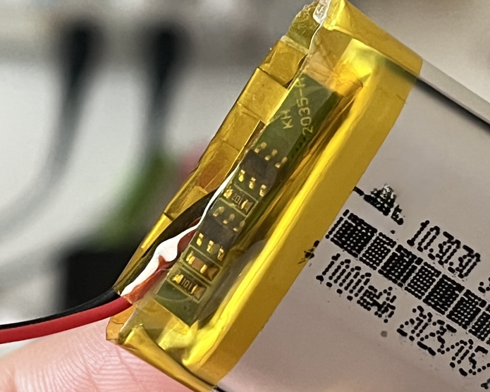
The function of this protective plate is very limited. It only provides the minimum protection.
Provides the most basic protection when the input voltage is higher than 4.4V, the voltage is lower than 2.1V, or there is a short circuit (excessive transient current).
The charging protection board uses the most basic components to ensure the high reliability and high sensitivity of the module.
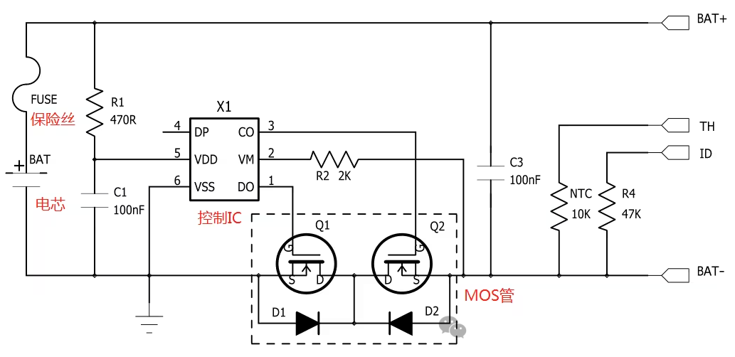
• According to the schematic diagram, the control IC monitors the status of the lithium battery and controls the on and off of the MOS tube to control the on and off of the charging circuit.
• The fuse prevents the control IC from failing and quickly disconnects the charging circuit if a short circuit with high current occurs.
Normal charging
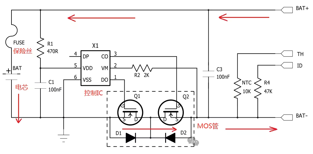
Overcharge protection
Control IC Pin5 detects overvoltage → turns off Q2 → charging circuit is shut down
• Recovery conditions
External charging voltage drops
The battery cell is partially discharged and the battery cell voltage drops
Normal discharge
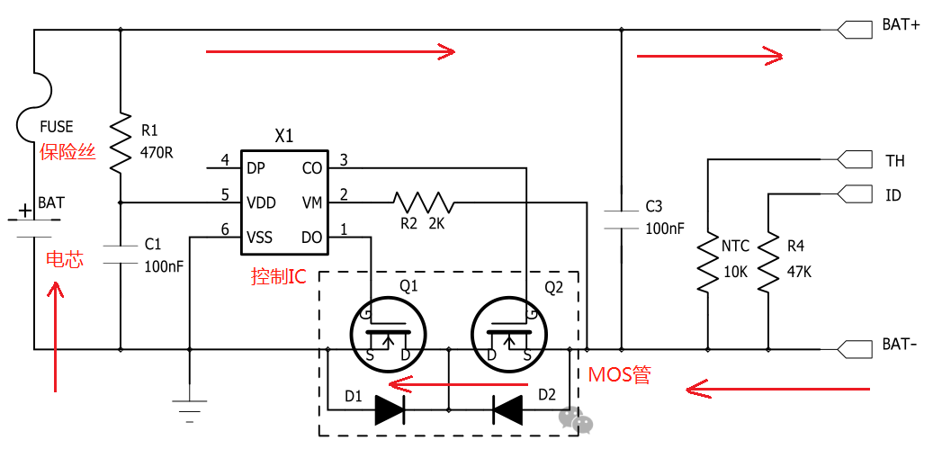
Over-discharge protection
The control IC Vdd-Vss voltage detects undervoltage → turns off Q1 → the discharge circuit is shut down
Short circuit overcurrent protection
Fuse - It will disconnect when there is a large transient current. This is to prevent the control IC from failing. It is a purely physical protection and the last guarantee.
The common practice now is to use the internal resistance characteristics of MOS to determine overcurrent.
Before the introduction, it is necessary to clarify
• The internal resistance of the MOS tube is about 30mΩ, and the total resistance of the two MOS tubes is 60mΩ.
• Theory: When a resistor passes 10mA current and 1A current, the voltage difference between the two ends is different.
Control IC by
• Voltage difference between the two ends of MOS Vds
• MOS internal resistance Rds
• The threshold set inside the control IC is generally 0.1v
According to Ohm's law
I = Vds / Rds = 0.1V / 0.06Ω ~ 2A
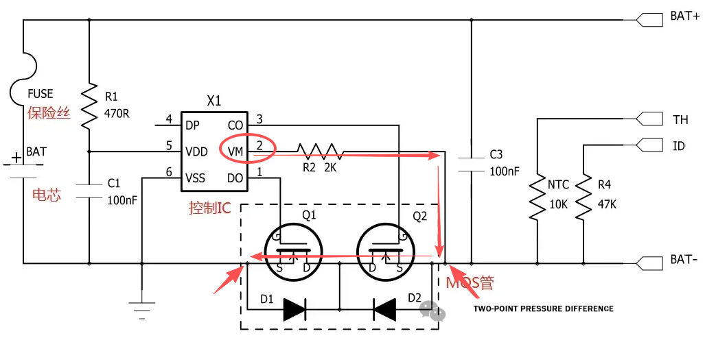
This is how the control IC detects voltage through Pin2. A slight voltage difference can trigger the threshold preset by the manufacturer.
Exceeding P2 exceeds the voltage threshold → determining overcurrent > 1A → shutting down the MOS tube → disconnecting the circuit.
determine overcurrent without adding additional devices .