EN

News
603450 3.7V 1200mAh LiPo Battery: Dimensions, PCM & Connectors
Quick answer. A 603450 3.7V 1200mAh LiPo battery is a single-cell rechargeable pouch battery in a size class commonly associated with approximately 6.0 mm thickness × 34 mm width × 50 mm length. These figures are a starting point for selection, not a guaranteed finished-pack size. The PCM, insulation, folded tabs and cable exit can change the space required. Before ordering, confirm the maximum assembled dimensions, electrical limits, protection configuration and connector pinout.
For OEM buyers, repair workshops and product developers, matching “603450” and “1200mAh” is only the beginning. A battery can have the expected capacity and still be unsuitable because its cable exits in the wrong direction, its protection circuit trips during startup or its connector polarity differs from the device.
This guide explains how to turn a basic battery description into a specification that engineering, purchasing and the battery supplier can approve together.
What Does the 603450 Battery Code Mean?
In a common pouch-cell naming convention, the digits describe the approximate cell dimensions. They do not define the complete electrical and mechanical specification.
| Marking | Common interpretation | What still needs confirmation |
|---|---|---|
| 60 | Approximately 6.0 mm thickness | Maximum thickness, tolerance and added insulation |
| 34 | Approximately 34 mm width | Maximum width and edge-seal arrangement |
| 50 | Approximately 50 mm length | Whether the dimension includes tabs and PCM |
| 3.7V | Nominal cell voltage | Approved charging limit and operating voltage range |
| 1200mAh | Stated capacity of 1.2Ah | Rated, typical or minimum capacity and test conditions |
Manufacturers may use different dimensional definitions and assembly arrangements. Always ask whether the quoted size describes the bare cell body or the complete protected battery.
For example, an LP POWER preliminary specification for its LP 603450 1200mAh battery lists an assembled length of 52 mm, with a width of 34 mm and thickness of 6 mm. This is a manufacturer-specific example of why the model code cannot replace a drawing. It is not a Cowon dimensional specification.
The stated voltage and capacity also allow a simple nominal-energy calculation:
Nominal energy = 3.7V × 1.2Ah = 4.44Wh.
This is calculated from the stated values. It is not a measured usable-energy result, and it does not establish discharge current, cycle life or compatibility with a particular device.
Cell Dimensions vs Finished Battery Dimensions
The space available inside the product should be compared with the maximum finished battery dimensions, including the agreed assembly materials.
A complete battery may include a PCM near the tab end, insulating tape, a product label, adhesive backing and cable strain relief. These details can affect fit even when the underlying cell belongs to the correct size class.
| Area to check | Why it matters | What to request |
|---|---|---|
| Cell body | Nominal dimensions do not describe every production tolerance | Dimensioned cell drawing |
| PCM and folded tabs | The protected assembly may extend beyond the cell body | Finished-pack drawing |
| Tape, label and adhesive | Added layers affect thickness and mounting | Complete assembly specification |
| Cable exit | Wires need a suitable route without pinching | Exit direction and routing allowance |
| Enclosure clearance | The lid, PCB or screw bosses may press against the pouch | Fit review in the assembled device |
Avoid a dimension string without an axis order. “50 × 34 × 6 mm” and “6 × 34 × 50 mm” may describe the same object, but they are easy to misinterpret during procurement.
Do not force a soft pouch into a tight cavity or use the enclosure to squeeze it down to the required thickness. Agree the necessary clearance and allowance for dimensional change with the supplier.
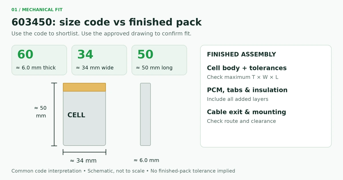
Common size-code interpretation, not a finished-pack drawing. Confirm maximum assembled dimensions before fixing the enclosure design.
For replacement projects, record the original mounting method, lead exit and cable route. A swollen old battery should not be used as the dimensional reference; use the original specification, device drawing or an undamaged reference part.
What Does the PCM Do?
A PCM is a protection circuit module. Depending on its design, it can interrupt charging or discharging when abnormal voltage, current or short-circuit conditions are detected.
Its thresholds, delays and recovery behaviour depend on the selected circuit. They are not defined by the “603450” model code.
Texas Instruments’ BQ2970 family provides an example of single-cell voltage and current protection using fault detection and external switching devices. This is a technical reference, not a statement that a particular Cowon battery uses this IC.
A protection trip threshold is not the battery’s permitted continuous current. The cell, switching devices, wires and connector must all support the intended load. Request the assembled battery’s continuous rating and a separate pulse specification, including pulse duration and repetition interval.
PCM vs Charger: Two Different Functions
A protected battery still needs an appropriate charging system. The charger controls normal charging, while the PCM responds to specified fault conditions.
| Item | Main role | What to confirm |
|---|---|---|
| Charger | Controls normal charging current and voltage | Compatibility with the exact cell specification |
| PCM | Responds to defined electrical faults | Thresholds, delays and recovery behaviour |
| Battery cell | Stores and supplies energy | Approved charge and discharge conditions |
| Device electronics | Draws power and manages device operation | Operating voltage, startup demand and cutoff behaviour |
For a conventional cell specified for a 4.2V charging limit, use a compatible single-cell constant-current/constant-voltage charger with settings approved for that battery. STMicroelectronics’ STBC08 illustrates this charging architecture; it is not a universal recommendation for every 603450 project.
Do not connect a bare LiPo battery directly to a 5V USB supply or use the PCM as the normal charge controller.
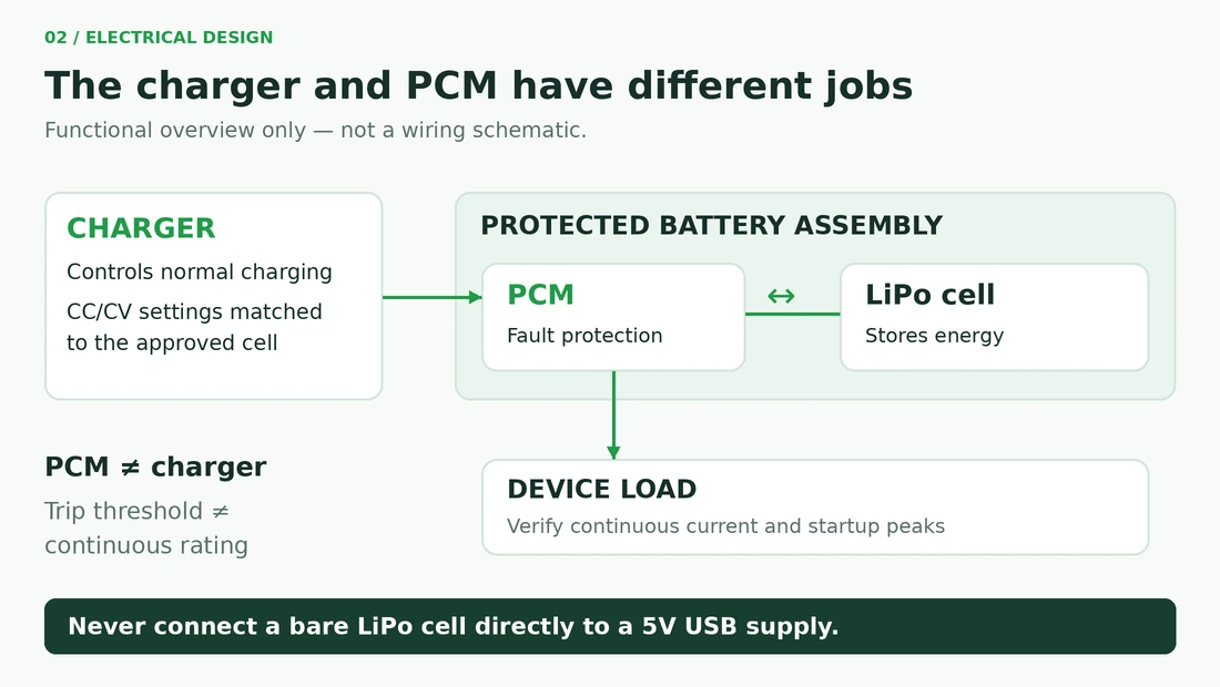
Functional overview only, not a wiring schematic. Charging control and battery protection must be specified separately.
Before approving the battery, establish whether protection is installed in the pack, the host device or both. Engineering should also check what happens when protection disconnects the battery and how normal operation resumes.
How to Specify the Correct Battery Connector
“Two-pin JST connector” is not a complete purchasing specification. Identify the manufacturer, series, housing, terminals and mating header, together with a documented pinout.
For example, the official JST PH series uses a 2.0 mm pitch, and JST lists a 2A rating with AWG 24 wire. That conditional connector rating does not prove that a particular 603450 battery can deliver 2A, or that an unidentified lookalike connector has the same rating.
1. Confirm the exact mating parts
Pitch alone is insufficient. Check the housing shape, keying, contact arrangement and mating direction. Use part numbers wherever possible.
2. Document positive and negative positions
Provide a connector-face drawing or clearly oriented photograph. State whether the view is from the mating face or the wire side.
A connector that fits physically does not establish correct battery polarity. Verify the agreed pinout before connection.
3. Define the cable specification
Record wire gauge, insulation requirements, lead length and tolerance. Define where the length is measured—for example, from the battery cable exit to the rear of the connector housing.
Wire colour is useful for inspection, but it should not replace a controlled wiring specification.
4. Identify any third-wire function
A third wire may serve temperature sensing, identification or another purpose. For an NTC arrangement, confirm nominal resistance, reference temperature, B value, sensor location and connection scheme.
Do not substitute a two-wire battery for a three-wire original without checking what the device expects.
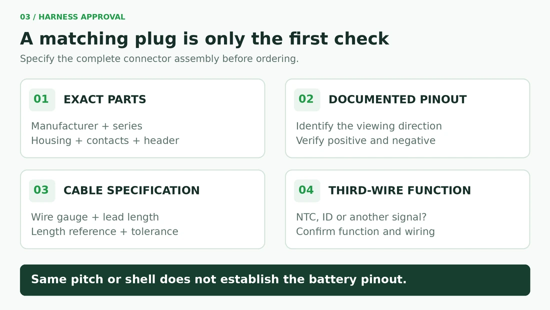
Confirm exact parts, pinout, cable details and any third-wire function. A matching connector shell does not establish replacement compatibility.
How Much Current and Runtime Can a 1200mAh Battery Provide?
Capacity describes stored charge, not unrestricted current capability.
For a 1.2Ah battery:
- 0.5C corresponds to 0.6A.
- 1C corresponds to 1.2A.
These are mathematical conversions, not confirmation that either rate is approved for the battery being purchased.
Separate average demand from peak demand. A device may consume little current during normal operation but draw a larger burst during radio transmission, motor startup or another event. Share the load profile with the supplier, including the lowest battery voltage at which the device must operate.
For an illustrative constant battery-side current of 200mA:
Ideal runtime = 1200mAh ÷ 200mA = 6 hours.
This assumes the full stated capacity is available. Actual runtime depends on the discharge conditions, device cutoff, temperature, ageing and load behaviour.
If 200mA is measured at a regulated output rather than at the battery, the simple division is not appropriate without accounting for voltage conversion. For a regulated load, use an energy-based estimate:
Runtime ≈ Usable battery energy × Conversion efficiency ÷ Output power.
Measure average output power over the actual operating cycle, then validate runtime with representative batteries installed in the finished device. A capacity label alone is not a runtime guarantee.
A Practical Procurement Checklist for OEM and Replacement Projects
A useful RFQ combines electrical requirements, a mechanical drawing and the harness definition.
| Requirement | Information to provide |
|---|---|
| Battery identification | 603450 size class, 1S configuration, 3.7V nominal and 1200mAh target |
| Capacity basis | Required minimum or rated capacity and agreed test conditions |
| Mechanical limits | Maximum assembled thickness, width and length |
| Installation | Mounting method, cable exit and available clearance |
| Load profile | Average current, continuous maximum, pulse demand and device cutoff |
| Charging | Charger specification, voltage limit, current and temperature requirements |
| Protection | PCM requirement and approved protection specification |
| Harness | Connector part numbers, pinout, wire gauge, length and sensor details |
| Project information | Application, sample quantity, expected volume and delivery schedule |
| Documentation | Drawings, specifications, traceability and required test documents |
During sample approval, check fit, cable routing, polarity, startup behaviour, charging and runtime against the agreed requirements.
Record the approved assembly revision so future orders do not depend on an informal description such as “the same 603450 battery.” Protection testing should follow an agreed procedure using suitable equipment and trained personnel.
Frequently Asked Questions
Is every 603450 battery exactly 6 × 34 × 50 mm?
No. Those figures describe a common size-code interpretation. Cell tolerances, dimensional definitions and assembly details vary. Use the maximum finished dimensions shown on the approved drawing.
Does 1200mAh mean the battery can continuously supply 1.2A?
No. It describes a stated capacity of 1.2Ah under defined conditions. A 1.2A load is numerically 1C, but the permissible continuous current must come from the battery specification.
Can I order a protected battery without choosing the PCM myself?
Yes, a supplier can propose a PCM based on your requirements. However, the final assembly still needs a documented protection specification. “Protected” alone does not define current capability or recovery behaviour.
Does a PCM replace the charging circuit?
No. The charger controls normal charging, while the PCM responds to specified fault conditions. Both must be compatible with the selected cell and device.
Will a two-pin connector make the replacement plug-and-play?
No. Confirm the mating parts and polarity, then check dimensions, charging requirements, load capability and any host-device requirements. Physical connector fit is only one part of approval.
What should I send Cowon for a quotation?
Send the available battery-space drawing, original battery details where applicable, current profile, charger information, connector pinout and required quantity. These give the technical team a practical basis for assessing the proposed assembly.
Next Step: Specify the Right 603450 Battery for Your Device
A suitable 603450 battery starts with more than a matching model code. The finished dimensions, electrical limits, PCM and wiring must work together inside the intended device.
Explore Cowon’s Li-Polymer Battery range, then contact Cowon with your battery dimensions, load requirements and connector details. Request confirmation of the complete proposed specification before sample approval or production ordering.
Technical references: LP POWER preliminary LP 603450 specification, Texas Instruments BQ2970 protection-device information, and JST PH connector specifications. Manufacturer examples explain general engineering principles and do not establish the specifications or installed components of a Cowon assembly. Energy and runtime examples are calculations, not product test results.